Some of you are blessed with the ability to drink coffee or tea at temperatures that seem to be approaching the temperature of lava. Unfortunately, I’m always trying to find ice or cold water to cool down my drink whether I just brewed it at home or bought coffee from a cafe.
So it is not surprising that a Smart Coaster Popular Science Build It project by Dave Prochnow caught my eye. This is a pretty simple circuit that uses a thermistor to measure the temperature of your hot drink. You calibrate your coaster to illuminate an LED while the temperature of the drink is too hot and to turn off the LED once the temperature reaches the point where it is cool enough to drink. I like the author’s use of a shoe polish container, but all I could get my hands on was an ever-so-versitile Altoids container.
Like the author explains, once you have your circuit built and tested, you need to calibrate your potentiometer to turn off your LED just when the temperature of your drink is ready to drink. I taped my thermistor to the underside of the top of the metal enclosure, but still found it a bit tricky to get the potentiometer set properly. When you are calibrating, you need to make sure you use the same type of coffee cup or else you will get very inconsistent results.
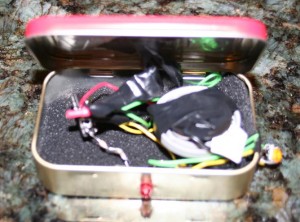
My finished product is below. As you can see, the LED sticks out the front and I also have my potentiometer sticking out the side of the enclosure. With the Altoids box, it is easy to have wires hang outside, but be careful as repeated open and closing quickly wears away the insulation on the wires!
I initially prototyped the circuit on a breadboard, like I do for any new circuit I’m building or experimenting with, and used a plastic (note metal would not be good here given that it would conduct and cause your battery to get extremely hot!) chip clip to hold the positive and negative leads onto each side of the flat, disc-shaped battery. In the enclosure I built a home made 3.7V battery holder by putting the battery in the top of an old 35mm camera film case and used hard plastic to cover the bottom. I cut a small hole in the top and bottom to route a wire with a long, uninsulated lead (that was swirled into a spring-like shape) into each side of the battery enclosure. Finally, I taped the home made battery enclosure with electrical tape to keep the positive and negative wires snug against each side of the battery. It looks pretty ugly, but works great.
Below is a picture of the inside of the enclosure where you will see the battery holder on right side, the tangled mess of wires and the thermistor taped with electrical tape to the bottom of the lid:
And I used the dead bug method to solder the LM324N Integrated Circuit (IC) into the circuit. This is a technique that is popular in robotics where space is limited. This technique is nothing more than turning the IC upside down, with the legs sticking up (so it looks like a dead bug on its back with its legs up in the air) and soldering your connections directly to the legs of the integrated circuit chip. If I had an IC socket handy I would have used the dead bug technique to solder directly to the empty socket and would have avoided the risk of damaging the circuit by soldering it directly. Fortunately, I did not damage the IC by soldering directly to it. By clipping the unused legs of the IC, it made it a bit easier to solder directly to the IC legs.
Finally, I’d highly recommend that you use a stripboard or create a printed circuit board for this circuit. The article does not advocate the use of a board and in the excitement to build the smart coaster I did not use a board…but shortly into the project remembered how frustrating it can be to solder everything together and then struggle to get the circuit into its enclosure without breaking any solder joint. With a strip or circuit board the circuit would easily sit in the enclosure with the LED, thermistor and potentiometer connected via lead wires.
In retrospect, I also recommend that you use very light gauge wire for any wires that will require flexibility and that you intend to move around. Otherwise, you end up breaking solder joints as you move the components around.
A few items worth noting if you are building this project:
- You can always identify leg 1 of an IC by finding the dimple in side of Integrated Circuit (IC) and then finding the first leg that is counter clockwise to the dimple. Sometimes, leg 1 also has a dot of paint near it. My LM324N IC had the dimple, but not paint. Below is the block diagram that displays the dimple at the top and leg 1 on the top left.

- I recommend that you purchase a battery holder for your 3.7v battery. Here is a battery holder available from SparkFun.com. You will still need to wrap your battery and holder in lots of electrical tape to make sure a metal holder does not conduct against the side of the smart coaster (assuming your enclosure is metal).
- I would highly recommend that you use a heat sink if you are soldering your IC using the dead bug technique. This will draw heat from the leg and minimize the chance of damaging your IC.
- Whether you use a board or not, you should make sure you have a helping hands or other desktop vice to hold your parts in place while you are soldering.
- Get some heat shrinking insulator material and slip the heat shrink tubes on your wires prior to soldering. This way you can easily cover your soldering joints and exposed metal inside your crowded, metal enclosure. And for places where you cannot easily use heat shrink tubing, use plenty of electrical tape.


