I’m starting a project to sense motion in our conference rooms at my office at SPR Consulting. We recently build a mobile web app that shows availability of conference rooms at our office. Currently, the web app shows availability based on the scheduling of the room resources in Microsoft Office 365. But we have a policy that rooms can be claimed if they are empty, so knowing whether a room is physical occupied is also important.
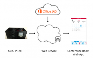
For this project, I’m creating a motion detection device that sits in each conference room and senses motion in the room. The device checks for motion and reports whether there is motion (conference room is occupied) or no motion (conference room is not occupied) and then sleeps for a configured number of seconds. Because the sensor checks whether a room is occupied and it uses a Raspberry Pi computer, the name “Occu-Pi-ed” seemed obviously appropriate.
The device reports the occupied status to a custom web service. Our conference room web app checks this occupied status and includes the status in the web app UI.
This blog will cover the first half of the project by covering the electronics and wiring of the project. The second half (not yet written) will cover the programming on the Raspberry Pi and physical packaging into a custom enclosure.
The project wiring is very simple, you only need the following parts:
- 1 Raspberry Pi with WiFi dongle, SD card and power cable
- 1 Pyroelectric Infrared PIR Motion Sensor Detector Module
- 3 female to female jumper wires
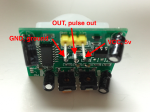
I was not able to find any data sheet on this exact board, so I’d like to share my findings to make it easier for others. The PIR motion detector board has 3 pins and they are labeled:
- VCC – is connect to the 5v pin 4 on the Raspberry Pi
- OUT – is the pulse out pin that is set to high if motion is detected and set to low if no motion is detected, which connects to pin 11 on the Raspberry Pi
- GND – is connected to the ground pin 6 on the Raspberry Pi
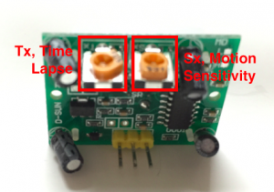
The PIR motion sensor has two potentiometers that allows adjusting the sensitivity of the motion sensitivity and time lapse (or stickiness of sensing motion). The potentiometers can be adjusted with a small screw driver. Be gentle and be aware the potentiometers only turns about 270 degrees. While holding the board with the potentiometers at the top and the sensor dome facing away, the left potentiometer (labeled Tx) adjusts the time lapse of the sensor. Turning the potentiometer clockwise causes the sensor to continue reporting motion even after the motion stops. Turning the potentiometer all the way counterclockwise causes the sensor to report whether motion is being sensed real-time. The rightmost potentiometer (labeled Sx) adjusts the sensitivity of the motion sensor. Turning the the potentiometer clockwise causes the sensor to be more sensitive to movement (especially farther away). Turning the potentiometer counterclockwise causes the sensor to be less sensitive to motion.
Why the adjustments?
- Time lapse – Most PIR sensors will be connected to a microcontroller (or circuit) that will be “listening” to the PIR board for the pulse pin to be raised high, to indicate movement. Depending on the implementation, the connected microcontroller may poll the pulse pin periodically. Time lapse allows the identification of motion to be propagated through the pulse pin after the motion is sensed, for a configurable amount of time. This is very useful if your microcontroller, is for example, checking for motion every 30 seconds and then sleeping. You could miss the motion if you are just checking at a given microsecond every 30 seconds, so the board can propagate the sensing of movement for a longer period of time to increase the chance that your board catches the movement. As you turn up the time lapse, the board increases the amount of time the pulse pin is high after sensing movement. From some playing around, it seems the potentiometer for time lapse is exponential and not linear, meaning that the time lapse gets dramatically longer as you turn the screw little by little. In my experimentation, if I turned the time lapse sensitivity to high, I waited over 15 minutes and the sensor was still sticky. Because I am impatient, I turned the sensitivity back down and unplugged the 5V jumper and plugged it back in to get back to a reasonable time lapse potentiometer setting.
- Motion sensitivity – From my experimentation, I found the sensitivity effected the distance more than any other aspect of its sensitivity. With the sensitivity set at its highest, it seems there may be some false positives, meaning the sensor every long once and a while pulses the output pin even though I was not aware of any movement in the room.
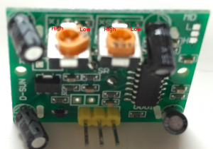
For my final configuration, I have the sensitivity turned all the way up (turned to High location on image above) and time lapse set to 1/3 of the way between Low and High. I have found this creates the pulse out that is high for about 1.5 minutes whenever motion is sensed.
Stay tuned, the next blog in this series will include the python programming on the Raspberry Pi as well as the physical packaging into a custom enclosure.
