I have been printing a lot of parts for various 2D and 3D bots. I have found pieces and parts online and am designing others myself. For pulleys and gears that mount to stepper motors, there needs to be a set screw to ensure the pulley/gear stays fixed in place on the rotating shaft of the stepper motor.
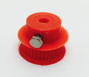
One set screw technique is to tap or carve threads into the printed plastic part, but the plastic threads can only support so much pressure and will likely eventually become stripped. A better approach is to design a part to have an embedded cavity to hold a metal nut. The set screw then threads through this embedded metal nut and provides pressure to hold the pully/gear in place.
This technique of embedding a nut in your printed piece is commonly referred to as a “captive nut”. If you consider embedding other things in 3D prints, all sorts of possibilities start to emerge. Large and complex designs can be broken into smaller pieces that are screwed/bolted together. And electronics, such as LEDs, can be embedded directly inside prints.
There are two things you need to do to embed something in your 3D print:
- Design your 3D object to have a cavity for the embedded object
- And then print it
However, this will be a very iterative process where you design, then print, then design, then print over and over until your piece is complete. Keep in mind that embeding objects into 3D prints is not just something you can do when designing your own parts from scratch, this is something that you can also do to augment an existing 3D object that you download from the Internet.
Designing for a captive nut
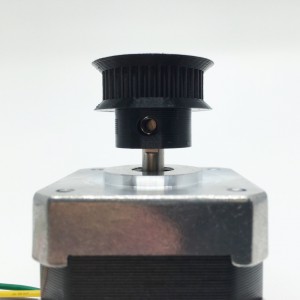
Back to my stepper motor gear as an example…I decided I wanted to use an M3 (3mm metric) screw and for the set screw. As a result, a M3 nut will be required to be embedded. The above picture illustrates how a set screw tightens perpendicular to the stepper motor shaft.
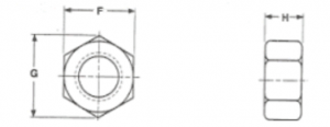
The first step is to measure all dimensions of the M3 nut. Although measurements are available online, I always measure my object to embed in case it is different. If you don’t have digital calipers, you need to get one and I’d recommend watching for a sales at Harbor Freight where you can them for as little as $12 USD. I measured 5.44mm across the flats (F), 6.18mm across the corners (G) and 2.24mm for its width (H).
Assuming your printer is calibrated perfectly, you will print parts that are the exact dimension as you have designed. Well, that is true for rectangular parts where there are just straight angles, but that is not true for circular details. This is because a circle is really made up of many points. The more points that are used to define the circle, the more accurate the curve will be. To illustrate how circles are modeled for 3D printing, see the image below of two cylinders modeled in Tinkercad. The orange cylinder is modeled using approximately 20 points to define the circle of the object. In contrast, the blue cylinder is modeled to use 100 points to define the circle of the object. Notice how well refined the blue circle appears vs the orange object. But the more important point is that, although both cylinders were designed with a 10mm hole, the blue hole is larger and closer to 10mm than the orange hole. Both objects will have a final printed hold smaller than 10mm, but the blue will be much closer to the desired diameter. The takeaway is to always design circular details with as many points (or dimensions in Tinkercad lingo) as possible. Note in Tinkercad, you have to use a community defined cylinder that allows the number of dimensions to be set.
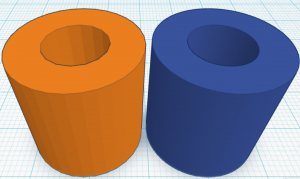
So, by definition, a circle is always smaller 3D printed than it was designed to be. So you always need to make sure your holes are oversized in your design to have the right finished print size.
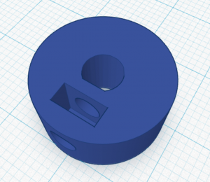
Aside from adjusting for circles, we also need to provide some wiggle room to make sure we can fit our part inside the printed cavity. Based on experience, and knowing some wiggle room is okay (I just cannot have so much wiggle room that my nut is able to spin while embedded), I decided to add about .4mm to the width (F) and height (G) and about .2mm to the depth (H). This resulted in the following dimensions for my cavity for my M3 nut: 5.8mm width (F), 6.6mm height (G) and 2.6mm depth (H).
The M3 screw is 3mm in diameter, but I decided to make the hole for the M3 screw to be 3.6mm in diameter knowing it must be designed oversized (see illustration above) and knowing that having it be a bit bigger than necessary will not be an issue. And after measuring the nut, I decided to have the bottom of the perpendicular hole 1.5mm above the bottom of our nut cavity. Below is a cross section of the shaft showing the cavity as designed:
Printing using a captive nut
Prior to printing, you need to slice your object and then examine the layers to identify when your printed cavity is fully printed, but no layers are yet printed on top of this cavity. This is the place where you need to pause your print, insert your nut, and resume your print. Most 3D printing software allows a print to be paused, and allows your print head to be jogged (in case it is blocking your cavity). Most software, including Simplify3D which I’m using, will relocate the print head to the right location after resuming printing.
The most basic way to pause your print is to know at which layer to pause, and to watch your print and manually pause at the right layer, manually insert your nut and manually resume. There is another more sophisticated technique to edit the gcode created by your slicer and I will cover this technique in a future blog. See the following movie that shows the slicer plan for the cavity with the cavity completely printed after layer 83:
It is critically important that you ensure that your nut is level to or below the surface of the top of your print when you pause and insert the nut. If the nut protrudes above the surface, it may damage your print nozzle.
Below is after layer 83, with the printer paused:
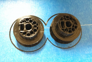
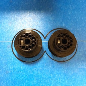
And the photo shows the cavity with the nut put in place:
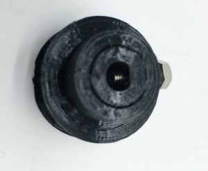
And this is the final printed piece:
Below is the gear set on a stepper motor:
Conclusion
Creating this cavity for a M3 nut and screw is really easy using tinkercad.com. I modified this 36 tooth GT2 gear from thingiverse.com and you can see my final work on tinkercad.com. Check out my object in tinkercad.com and ungroup it to see the objects used to create the cavity and holes.
Leave a Reply