First some background, I’ve calibrated my Printrbot Plus 3D printer’s extruder (using Repetier v0.56 for Mac and Slicer for Mac v0.9.9) to make sure the flow of filament is accurate using Josh Marinacci’s super simple technique (see Calibrating the Extruder section of this page). And I periodically check the accuracy of my prints by printing Matthew Croucher’s 5mm calibration cube.
The height and width of my prints are very accurate to their intended dimensions, but I struggle with small parts or small details that extend out from the faces of my models, especially toward the top of my prints. See this image of the 5mm calibration cube as an example.
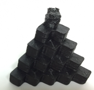
The overall print quality and dimensions are accurate and square, but the top 5mm cube is very deformed. What’s more interesting is that the cube starts okay (although that is hard to see in the photo) for the first 3-4 layers of the top cube look pretty good and form a base of the square. But for layers 5+ of the top cube, it quickly becomes very deformed.
It becomes deformed because the hot end that is extruding is running in such a tight/small area, that the filament never gets a chance to cool properly. Using Repetier/Slic3r, the extruder does not have a configurable option to slow down for just the top of the cube and the filament does not have a chance to cool properly. Sure, I could slow down the entire print to be a speed that is okay for the top to print properly, but that would make a 20 minute print take hours, which is not acceptable. As the top of the cube is printed, lower layers of filament are not cooling and are not stable, so subsequent layers pull on the lower layers and cause it to be deformed. The problem is further worsened by the filament getting stuck to the bottom of the extruder’s hot end and causes the filament to be further deformed.
There are several solutions to my issue, the two primary being:
1. Create a cooling tower to create additional work for the extruder in order to allow the top cube to cool properly.
2. Use other CAM software that allows speed to be configured for small print areas.
In this blog I will be describing technique #1, the use of a cooling tower to print small areas. A cooling tower is just a separate object to be printed that is the same height or higher than the piece that requires cooling. This could be a duplicate of the object you are printing, or in my case, a simple 10mm diameter cylinder the same height as the piece I am printing. For the 5mm cube to be printed properly, I needed a 25mm tall cylinder. The cooling tower requires the extruder to move from your main piece to a secondary (sometimes throw away) piece and as it moves back and forth printing both pieces, it allows time for your primary piece’s layers to cool. The width of your cooling tower will allow you to determine the amount of time spent away from your primary piece. The time it takes to print the cooling tower is most of your cooling time. However, the travel distance from your two pieces (as physically laid out in your CAM software) will also provide a small fraction of additional time for your layer to cool on your primary piece.
Below are the steps to create a 25mm high cooling tower in SketchUp Make v15.2.686 for the Mac:
1. Create a new model
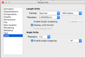
2. If necessary, adjust the the units of your model to have format of Decimal/Millimeter by adjusting the settings on the Window | Model Info dialog’s Units tab as show below.
3. Select the Circle tool ![]() and click ONCE on the canvas and then click on the Radius box in the bottom right corner of the window and type 6mm or whatever diameter you want for your cooling tower, then press Return key on keyboard
and click ONCE on the canvas and then click on the Radius box in the bottom right corner of the window and type 6mm or whatever diameter you want for your cooling tower, then press Return key on keyboard ![]() .
.
4. Select the Select tool ![]() and click on the circle. Don’t worry if your colors are different, but you should see that the circle is selected you click on it. On my mac, the selected surface is shaded.
and click on the circle. Don’t worry if your colors are different, but you should see that the circle is selected you click on it. On my mac, the selected surface is shaded.
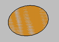
5. Select the Push/Pull tool ![]() and click ONCE on the circle’s surface that is already selected, then click on the Distance box in the bottom right corner of the window and type 25mm or whatever height you want for your cooling tower, then press Return key on keyboard.
and click ONCE on the circle’s surface that is already selected, then click on the Distance box in the bottom right corner of the window and type 25mm or whatever height you want for your cooling tower, then press Return key on keyboard. ![]()
6. You should have a cylinder that is the exact height and width you specified.
7. You can double check the height and width by selecting the Tape Measure tool ![]() and then clicking on opposing sides of the circular top or top and bottom to check the height of the piece.
and then clicking on opposing sides of the circular top or top and bottom to check the height of the piece.
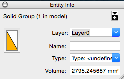
8. Select the Select tool ![]() and click on the top circle of the tower. Then, triple click the top circle again, and it will select your entire model. Carefully right click your fully-selected model and select “Make Group” from the context-sensitive menu. (Note: Although not super intuitive, the Explode menu item will ungroup your model). Then, open the Entity Info dialog from Window | Entity Info menu item. Once opened, verify the dialog indicates that your model is a solid group as shown below. This is critical as your model will not print properly if it is not solid.
and click on the top circle of the tower. Then, triple click the top circle again, and it will select your entire model. Carefully right click your fully-selected model and select “Make Group” from the context-sensitive menu. (Note: Although not super intuitive, the Explode menu item will ungroup your model). Then, open the Entity Info dialog from Window | Entity Info menu item. Once opened, verify the dialog indicates that your model is a solid group as shown below. This is critical as your model will not print properly if it is not solid.
9. Optionally, install the Solid Inspector extension by searching on “Solid Inspector” from the Window | Extension Warehouse search window. Click on Solid Inspector and download and install it.
10. With your grouped model selected, select Tools | Solid Inspector and verify in the resulting dialog that there are not errors, meaning that your object is solid.

11. If not already installed, download and install the STL export extension by searching on “SketchUp STL” from the Window | Extension Warehouse search window. Click on SketchUp STL and download and install it.
12. Once installed, make sure you grouped model is selected and select File | Export STL… In the resulting dialog, make sure you check the box to only export the selected model and use Millimeter as units. You can select either ascii or binary, binary is my preferred format because it is a smaller file. Finally click Export button to save your file to your local machine. Give it a descriptive name so you know what the STL file represents weeks or months from when you create it.
13. Using your CAM software of choice, drop the cooling tower as well as your piece to be printed on your virtual printing surface. And adjust their positions so they are at least a few inches apart.
14. Ultimately, you can create new cooling towers that are smaller in diameter to minimize the amount of filament required to make the tower. Or, get fancy and build a tower that starts thinner and expands in diameter at higher layers to correspond with the need for more cooling as the print gets toward the end.
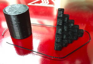
Here are the results from printing PLA on my Printrbot Plus (heated glass bed with temps: extruder 230 C, bed 80 C, the glass bed lightly coated with Vidal Sassoon extra firm hold #4 hairspray.
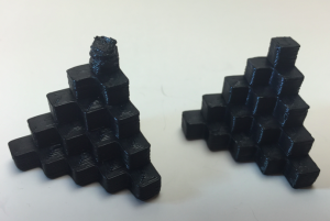
And here is a comparison of the test piece on right that incorporated a cooling tower and piece on left that did not use a cooling tower. The difference is quite dramatic.
Leave a Reply